#arduino uno r3
Explore tagged Tumblr posts
Visit Tumblr Blog
Explore Tumblr blogs with no restrictions, modern design and the best experience.
Last Seen Tumblr Blogs


Fun Fact
Tumblr has a 66 index score for customer satisfaction in the US.
Text
Arduino UNO R3 Board ATmega328P DIY Kit | Diykit Solutions
Explore the Arduino UNO R3 Board ATmega328P DIY Kit from Diykit Solutions! Unleash your creativity in electronics and robotics with high-quality materials sourced from trusted suppliers.
Arduino UNO R3 Board ATmega328P DIY Kit
0 notes
Text
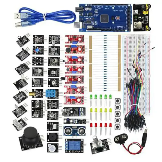
Arduino UNO R3 Based Advance Starter Kit
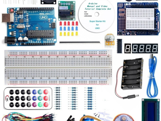
Regardless of your level of familiarity with Arduino, this Arduino UNO R3 Based Advance Starter Kit provides an enjoyable opportunity to broaden your understanding.
Constructing original and uncomplicated projects is an excellent method for gaining experience in coding and understanding basic electronic circuits.
This kit provides all the essential components for exploring electronics with an Arduino, plus additional items to advance your skills from a beginner to an enthusiast level. It contains all the essentials, including an UNO board, breadboard, cables, LEDs, resistors, and pushbutton switches.
An ideal choice for robot prototyping, as it comes with a variety of valuable components such as Servo motors, Ultrasonic sensors, Relays, and LCD modules. Additionally, it also includes several useful component kits like an RFID kit and a water sensor specifically designed for automating planting projects.
Included are the characteristics, qualities, and capabilities that this product has to offer.
Discover the convenience of an all-in-one kit that serves as an excellent introduction to coding.
Ideal for Beginners in Arduino Programming
This pack offers a range of components for experimenting with various projects.
#electronic components#sales in chennai#arduino#robotic kits#Arduino UNO R3 Based Advance Starter Kit
1 note
·
View note
Text
The Arduino Uno R3 is an ATmega328P microcontroller-based development board. This is widely popular in Embedded electronics because of the available resources and easy to use by everybody features. With 14 digital input/output pins where 6 can be configured and used as PWM outputs, 6 as analog inputs is a great addition for I/O related operations. Powered with a 16 MHz ceramic resonator, an USB connection, a power jack, an ICSP header, and a reset button.
2 notes
·
View notes
Text
シンセ開発ログ 2023-07-08: Pico用フリーシンセ「PRA32-U」を開発中/「Maker Faire Tokyo 2023」に出展予定/Pico用DAC基板の心配
「Digital Synth PRA32-U」は、Raspberry Pi Picoとオーディオ用DAC基板(Pico Audio Packなど)を使った、誰でも作れるシンセサイザー(MIDI音源)です。ソースコードはフリーで、Arduino IDEを使って改造できます。最初のバージョン(v0.1)はArduino UNO R3用シンセサイザー「Digital Synth VRA8-U」を移植したもので、これをベースに改善や機能追加を進めています。
このシンセは、10/14(土)~15(日) に東京ビッグサイトで開催される「Maker Faire Tokyo 2023」に出展予定です。「Maker Faire Tokyo」のメイン作品で、Arduino UNO R3を使わないのは初めてです。よろしくお願いします。
最近できたこと
サンプリングレートを31.25 kHzから48 kHzに変更(CPUスピードは120 MHz)
オシレーターの周波数精度を改善
オシレーターの周波数をVRA8-Uと同じようにずらす、デチューンを実現
モノフォニックモードでのオシレーター2の周波数を改善
オシレーター1がパルス波でも、サブオシレーターを有効化
位相変数のラップアラウンド発生時、ゼロクロス点近くで波形テーブルを切り替えるように改善(※パルス波は未対応)
フィルターの計��精度を改善(乗算の1回は32ビット×32ビットに)
カットオフ周波数の変化幅を8オクターブから10 + 7/12オクターブに(滑らかさは未調整)
LFOを改善(※フェードタイムは修正中)
EGを改善(カウンタを廃止して、乗算のみで減衰計算することで、処理時間を安定化)
コーラスエフェクトを改善(線形補間の導入で、高音でのプツプツが聞こえなくなる)
I2S DACのミュート解除処理を追加
READMEにPimoroni Pico VGA Demo Baseへの対応方法を追記
CPU負荷を安定させるために、条件分岐を減らす(継続中)
v1リリースまでに、まだまだやることがありそうです。また、基本的に音質はアップしていますが、細かい音質調整が後回しになっているのは不安なところです。
8月までには、音が新しくなったv0.2をリリースしたいと考えています。
なお、v2ではフィルターのローパス、ローカットモード切り替え、オシレーター2のリングモジュレーション、ハードシンク対応などを検討しています。
Pico用DAC基板の心配
Pimoroni公式ページでは、Pico Audio Pack(DACはTI/BB PCM5100A)の「Out of stock」が続いています。
https://shop.pimoroni.com/products/pico-audio-pack?variant=32369490853971
先日には、スイッチサイエンスでも「売り切れ」になってしまいました。
https://www.switch-science.com/products/7380
このままでは他のお店でも売り切れになり、「PRA32-U」を簡単に作れなくなるかも知れません。RP2040を使用したハード設計見本であるPimoroni Pico VGA Demo BaseもDACを積んでいるので対応をうたいますが、このボードには他のHATと組み合わせにくいなどの難点があります。
WaveshareのPico-Audioは代替ボードの有力候補で、Waveshareの他のボード(Pico LCD 1.14など)との相性も良かったのですが…なんとRev2.1 VersionでDACが変更され、Initial VersionのTI/BB PCM5101A(384 kHzまで)から、MCLK入力が必要なCirrus Logic CS4344(192 kHzまで)に変わってしまいました。(各社の販売ページでは、説明に混乱が見られます…)
https://www.waveshare.com/wiki/Pico-Audio
そもそも、現���入手しやすいMCLK入力不要なDACは、TI/BB PCM5100A、PCM5101A、PCM5102A以外では、NXP UDA1334A(96 kHzまで)くらいのような気がします。(PimoroniやWaveshareの様子を見ると、 PCM5100Aシリーズは入手困難になっているのかも知れませんが…)
現在、Arduino-Pico(Earle F. Philhower, IIIさんによるArduino IDEのRaspberry Pi Pico/RP2040用コア)ではI2SのMCLK対応が進んでいるので、こちらに期待しています。PRA32-Uでも、Waveshare Pico-Audio Rev2.1が使えるようになると思います。
https://github.com/earlephilhower/arduino-pico/issues/1065
Digital Synth PRA32-U v0.1.2リリース
https://github.com/risgk/digital-synth-pra32-u/releases/tag/v0.1.2
I2S_DAC_MUTE_OFF_PINおよびI2S_SWAP_BCLK_AND_LRCLK_PINS設定と、Pico Audio Pack用のミュート解除処理を追加しました。これまでミュート解除せずに音が出ていたのは「たまたま」でしょう。(まだ、音は新しくなっていません)
【2023-08-10追記】説明には「We also offer a MUTE pin which can be used to silence the output」と書いてありますし、さすがにMUTEピンはプルアップされている気がしてきました。
Digital Synth VRA8-U v2.2.3リリース
https://github.com/risgk/digital-synth-vra8-u/releases/tag/v2.2.3
PRA32-Uの移植元でもある、Arduino UNO R3用フリーシンセです。PRA32-U開発中に問題を見つけたので、モノフォニックモードでのオシレーター2の周波数を修正しました。

3 notes
·
View notes
Text
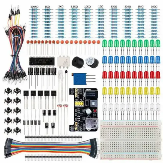
Electronic Components Circuit Breadboard Pack for Arduino Starter Kit The electronic parts suit for electronics program beginner to study the programming for Aruino serial development board,like Dev Board for Arduino Uno R3,Mega R3 etc.Electronic components Circuit Breadboard Pack list contain below: - 1x Power Supply Module Warning: Do not use voltage higher than 9V - 1pcs 830 Connection Point Breadboard - 1pcs 65 Jumper Wire - 140pcs Solderless Jumper Wire - 20pcs Male to Female Dupont Wire - 2pcs Pins (40pin) - 1pcs Precision Potentiometer - 2pcs Photoresistor - 1pcs Thermistor - 5pcs Diode Rectifier (1N4007) - 5pcs NPN Transistor (PN2222) - 1pcs IC 4N35 - 1pcs IC 74HC595 - 1pcs Activity Buzzer - 1pcs Passive Buzzer - 10pcs Push Button (Small) - 10pcs 20pf Ceramic Capacitor - 10pcs 103 Ceramic Capacitor - 5pcs Electrolytic Capacitor (100UF 25V) - 5pcs Electrolytic Capacitor (100UF 50V) - 10pcs white LED - 10pcs yellow LED - 10pcs blue LED - 10pcs green LED - 10pcs red LED - 1pc RGB LED - 10pcs resistor (10R) - 10pcs resistor (100R) - 10pcs resistor (220R) - 10pcs resistor (330R) - 10pcs resistor (1K) - 10pcs resistor (2K) - 10pcs resistor (5K1) - 10pcs resistor (10K) - 10pcs resistor (100K) - 10pcs resistor (1M) More other electronic component kits below: Interested with much more quantity to this Circuit Breadboard Pack,contact us to talk wholesale price support.Know more about our company,view here. Read the full article
0 notes
Text
Warum der Arduino trotz ESP32 & Co. nicht ausgedient hat

„Arduino? Das nutzt doch heute keiner mehr…“ Wer sich in den letzten Jahren mit Mikrocontrollern beschäftigt hat, stolpert überall über den ESP32. Dual-Core, WLAN, Bluetooth, 240 MHz, massig Speicher – und das alles für ein paar Euro. Kein Wunder also, dass der gute alte Arduino UNO im Schatten der neuen Mikrocontroller-Generation zu stehen scheint. Die Kommentare in Foren und Social Media klingen dann auch oft so: „Warum noch einen Arduino benutzen, wenn es doch den ESP32 gibt?“ Aber ist das wirklich so? Hat der Arduino tatsächlich ausgedient? Oder gibt es gute Gründe, auch heute noch auf den betagten Klassiker zu setzen? Und vor allem: Wenn ich gerade erst einsteige – sollte ich dann überhaupt noch mit einem Arduino anfangen, oder direkt auf einen ESP32 setzen? Genau um diese Fragen geht es in diesem Beitrag. Und so viel sei schon mal verraten: Leistung ist nicht immer alles.
ESP32 – das moderne Powerpaket (aber nicht für alles nötig)
Wenn man sich heute in der Maker-Szene oder auf YouTube umschaut, könnte man fast glauben, es gäbe nur noch den ESP32. Und das ist auch gar nicht so abwegig: Der ESP32 bringt schon ab Werk eine ganze Menge beeindruckender Features mit, die früher nur mit viel zusätzlicher Hardware möglich waren. 🔥 Ein kurzer Blick auf die Highlights: - Dual-Core mit bis zu 240 MHz - WLAN und Bluetooth direkt integriert - Bis zu 520 kB RAM und mehrere Megabyte Flash - Viele GPIOs, PWM, ADC, DAC, I2C, SPI, CAN, Touch-Sensoren, … - Bereits ab ca. 3 € (je nach Ausführung und Händler)
ESP32-S3-Matrix
ESP32-C3 mit LiPo Batterie
zwei Elecrow CrowPanels 2,4" & 5.0"
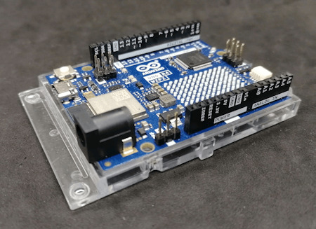
Arduino Nano ESP32
Generic-ESP32 Mikrocontroller

ESP32-C3 Super Mini

ESP32-S3-Zero Und dann wäre da noch ein echter Publikumsliebling: die ESP32-CAM.

Vergleich ESP32-CAM und ESP32-S3 CAM

ESP32-CAM mit externer Antenne und Board

ESP32-CAM

ESP32-CAM Modelle Für rund 5 € bekommt man hier nicht nur die Rechenpower des ESP32, sondern auch gleich eine kleine Kamera mit bis zu 5 Megapixeln dazu. Damit sind Projekte wie: - Überwachungskamera, - QR-Code-Scanner, - Fotos per E-Mail oder Telegram senden ganz einfach umsetzbar – ohne zusätzliche Hardware. Der Raspberry Pi Pico (RP2040) mischt kräftig mit – und bekommt Verstärkung Doch der ESP32 ist nicht allein auf dem Platz. Der Raspberry Pi Pico mit seinem RP2040 Dual-Core Cortex-M0+ Prozessor (133 MHz) hat sich schnell als leistungsfähige und günstige Alternative etabliert – und das in mehreren Varianten: BoardWLANBluetoothBesonderheitenRaspberry Pi Pico❌❌Basisversion, ohne FunkRaspberry Pi Pico W✅✅ (per Firmware)WLAN onboard, BT aktivierbarRP2350-Boards❌❌Mehr Power, keine Funkmodule (derzeit)


RP2040:bit
Melopero Cookie RP2040
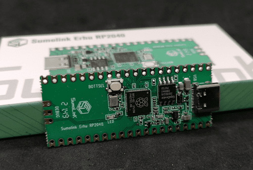
Sumolink Erhu RP240

Mikrocontroller - XIAO RP2040 & Raspberry PI Pico

Raspberry Pi Pico 2 - RP2350A

XIAO RP2350 Mit dem neuen RP2350-Chip steht mittlerweile ein leistungsstärkerer Nachfolger in den Startlöchern. Er wird derzeit auf einigen neuen Boards verbaut (z. B. auf Prototypen oder Dev-Boards asiatischer Hersteller) und bringt: - Höhere Taktraten (bis 200 MHz möglich), - Verbesserte Peripherie, - Und bleibt trotzdem kompatibel zur RP2040-Familie. Was aktuell noch fehlt: WLAN und Bluetooth sind (noch) nicht integriert – was den Chip für reine IoT-Projekte (noch) weniger attraktiv macht, aber für USB-HID oder Highspeed-Sensoranwendungen interessant sein kann.
Arduino – Der Klassiker mit Kultstatus (und vielen Gesichtern)
Wenn man „Arduino“ sagt, denken viele sofort an das gute alte Original: Arduino UNO R3, Made in Italy, stabil, bewährt – aber auch nicht ganz billig. Und genau da beginnt der kleine Konflikt, den vermutlich viele kennen: ➡️ Das originale Board unterstützt die Plattform, die Entwicklung und das Open-Source-Projekt. ➡️ Aber: Der Preis liegt oft bei 20 € und mehr – während Clones für 2–3 € zu haben sind. Doch: Genau das ist eben auch der Spirit von Open Source. Die Arduino-Plattform wurde so entwickelt, dass jeder (mit Einhaltung gewisser Auflagen) eigene Boards bauen und verkaufen darf. Und das tun viele Hersteller – vor allem in Asien. Dabei gibt es längst nicht nur einfache UNO- oder Nano-Kopien. Die Vielfalt an Arduino-kompatiblen Boards ist inzwischen riesig: Board / CloneBesonderheitPreisbereichNano Clone (CH340G)Klassiker für einfache Projekte2–4 €Pro MiniOhne USB, super klein und sparsam2–4 €Nano mit integriertem OLEDAnzeige direkt am Mikrocontroller4–8 €Nano mit 2,4 GHz Funk (nRF24L01) oder 433 MHz ModulIdeal für Funkprojekte ohne WLAN5–10 €Nano mit ESP8266-Modul onboardWLAN-fähig, bleibt aber Arduino-kompatibel5–10 €Nano mit Bluetooth HC-05 oder HM-10Kabellose Kommunikation über BT Classic oder BLE5–10 €

Arduino Nano mit nRF24L01 Erweiterungsboard

Microcontroller BLE-Nano von Keywish

Arduino UNO R3
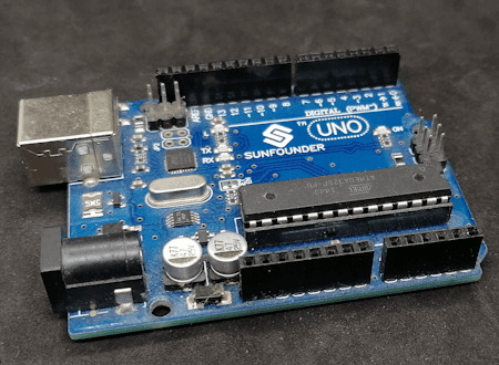
Arduino UNO R3 Clone von der Firma Sunfounder


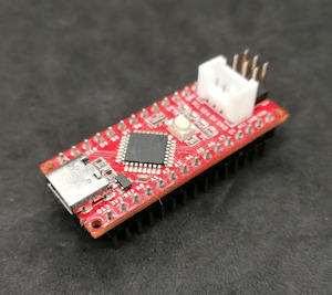
Arduino Nano V3 , ATmega328P

Arduino Mega 2560 Pro mini

Arduino Nano V3
Seeeduino Nano Gerade diese Vielfalt an spezialisierten Clones und Abwandlungen ist ein echter Vorteil: Man wählt sich für sein Projekt genau die Features, die man braucht – und spart sich den Ballast von Funktionen, die gar nicht benötigt werden. ➡️ Keine WLAN-Probleme, wenn das Projekt gar kein WLAN braucht. ➡️ Keine Bluetooth-Komplexität, wenn ein simples Relais geschaltet werden soll. ➡️ Aber: Wenn ein Display gewünscht ist, einfach ein Clone mit integriertem OLED nehmen. Teures Original oder günstiger Clone? Das Original aus Italien unterstützt natürlich die Entwickler, die die Plattform erst möglich gemacht haben. Gerade wenn es um professionelle Projekte, Support oder Weiterentwicklung geht, ist das ein guter Grund, auch mal bewusst zum Original zu greifen. Wer dagegen einfach ein kleines Hobby-Projekt umsetzt oder ein günstiges Board für Lernzwecke sucht, wird vermutlich bei einem Clone aus Fernost landen – und das ist auch okay so. Beides hat seine Berechtigung. Im nächsten Abschnitt schauen wir uns an, warum diese Einfachheit und Flexibilität dem Arduino einen Platz auf dem Basteltisch gesichert haben – auch wenn ESP32, RP2040 & Co. daneben liegen. Clone statt Frust: Warum gerade Anfänger mit günstigen China-Boards besser fahren Seien wir ehrlich: Wer mit Mikrocontrollern anfängt, wird früher oder später mal einen Fehler machen. Ein Kabel verpolt, einen Pin aus Versehen kurzgeschlossen, eine Lötstelle zu heiß… ➡️ Passiert. Gehört zum Lernen einfach dazu. Wenn dann das teure Original-Board abraucht, ist der Frust groß – und das Projekt vielleicht erst mal gestorben. Anders sieht es aus, wenn das eingesetzte Board nur 2–3 € gekostet hat. Dann bestellt man sich einfach ein neues und weiter geht’s. Genau deshalb finde ich: ➡️ Gerade Anfänger sind mit einem günstigen Clone gut beraten. Das senkt die Hemmschwelle, etwas auszuprobieren, und macht es viel leichter, aus Fehlern zu lernen. Ob Arduino Nano Clone, Pro Mini oder einer der vielen China-Nachbauten mit Zusatzfeatures wie OLED oder Funk – hier kann man für kleines Geld experimentieren, lernen und Spaß haben. Und wenn das Projekt später stabil läuft und vielleicht sogar „ernsthaft“ eingesetzt werden soll, kann man immer noch überlegen, ob man auf ein höherwertiges Original umsteigt.
Wann ESP32, wann Arduino? – Entscheidungshilfe für Projekte
Natürlich ist es immer verlockend, einfach zum leistungsstärksten Mikrocontroller zu greifen. Aber genau das ist oft gar nicht nötig – und manchmal sogar umständlicher. Denn: Der beste Mikrocontroller ist der, der genau das kann, was dein Projekt braucht – nicht mehr und nicht weniger. Um dir die Wahl etwas leichter zu machen, hier eine kleine Entscheidungshilfe: ProjektideeEmpfehlungWarum?Blinkende LEDs, Relais steuern, Taster abfragenArduino UNO, Nano, Pro MiniEinfach, stabil, günstig, kein OverkillLCD/OLED-Anzeige mit Temperatur-/FeuchtesensorArduino oder PicoWLAN meist nicht nötig, einfache UmsetzungDaten per WLAN ins Netz (z. B. ThingSpeak, MQTT)ESP32, Pico WWLAN/BT bereits integriert, viele Beispiele vorhandenMobile Projekte mit Akku und langer LaufzeitPro Mini (mit LowPower-Mod) oder ESP32 mit Deep SleepStromsparend, je nach FunkbedarfKamera-Projekte (Foto/Video-Streaming)ESP32-CAMKamera onboard, einfache EinbindungUSB-Tastatur-Emulation, MacroPads, HID-GeräteArduino Leonardo / Micro oder Raspberry Pi Pico (RP2040)Beide unterstützen native USB-HIDFunkprojekte ohne WLAN (z. B. 433 MHz, nRF24L01)Arduino Nano Clone mit FunkmodulKein unnötiges WLAN, einfache FunkanbindungEchtzeitkritische Anwendungen mit viel GPIO und TimingRP2040 oder RP2350Schnelles Realtime-Processing dank PIO, viele GPIOs 💡 Zusatz-Tipp: Für USB-Tastatur-Emulation (z. B. MacroPads oder automatisierte Eingaben) ist der Arduino Leonardo eine super Wahl, weil er den ATmega32u4 verwendet, der USB nativ unterstützt. Alternativ funktioniert das auch mit dem Arduino Micro oder dem Raspberry Pi Pico (RP2040), dort oft über die TinyUSB-Bibliothek.

Keyestudio Leonardo

Arduino Leonardo Clone

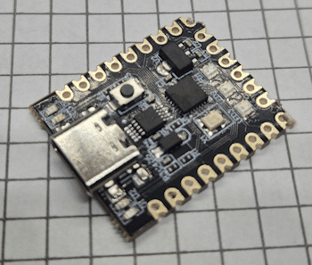
Mini RP2040 Developmentboard
Fazit: Alt, aber alles andere als nutzlos!
Ja, der ESP32 ist ein echtes Powerpaket. Ja, der Raspberry Pi Pico (RP2040) mischt kräftig mit und hat auch seinen Platz auf dem Basteltisch. Und ja – es gibt mittlerweile zig Alternativen mit WLAN, Bluetooth, Kamera, HID und noch viel mehr. Aber: Gerade das macht den guten alten Arduino so sympathisch: Er will gar nicht alles können – sondern einfach das, was man für viele kleine bis mittlere Projekte wirklich braucht. Ein Relais schalten? Ein paar LEDs blinken lassen? Einen Sensor auslesen und auf dem Display anzeigen? ➡️ Warum dafür einen Dual-Core mit WLAN bemühen, wenn es ein Nano für 3 € auch tut? Und genau das ist der Punkt: 🔹 Der Arduino ist einfach. 🔹 Er ist stabil. 🔹 Er hat eine riesige Community und viele erprobte Bibliotheken. 🔹 Er eignet sich perfekt zum Lernen – und bleibt auch danach oft die pragmatische Wahl. Gerade Anfänger profitieren enorm davon, sich nicht direkt mit komplexen Themen wie WiFi-Stack, Sleep-Modes oder USB-Treiberherausforderungen herumschlagen zu müssen. Und: Auch fortgeschrittene Bastler greifen gerne zum „alten Bekannten“, wenn es mal schnell, unkompliziert und robust sein soll. Mein Fazit: Der Arduino hat seinen festen Platz – auch im Jahr 2025. Nicht überall, aber da, wo „Keep it simple“ gefragt ist, ist er oft genau die richtige Wahl. ➡️ ESP32, RP2040 & Co. sind keine Gegner – sie sind Mitspieler im Team der Mikrocontroller. Die Kunst ist es, je nach Projekt den passenden Baustein auszuwählen. Jetzt bist du dran! Arbeitest du noch mit dem Arduino? Oder hast du komplett auf ESP32, RP2040 & Co. umgestellt? Welche Projekte hast du schon umgesetzt – und welcher Mikrocontroller war dafür die beste Wahl? 👉 Schreib es mir gerne in die Kommentare – ich freue mich auf den Austausch! Read the full article
0 notes
Text
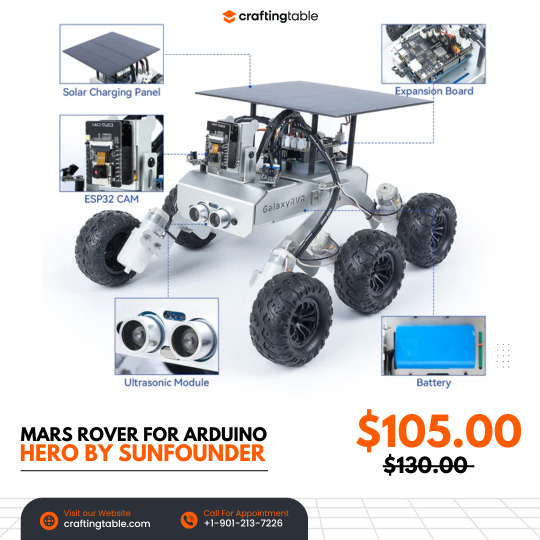
GalaxyRVR is an easy-to-use robot that works with Arduino Uno R3 and lets you experience what it’s like to explore Mars. It’s built strong with metal parts and has a smart wheel system to move smoothly over sand, rocks, grass, and even mud. It uses solar power to charge and has a camera (ESP32-CAM) that shows you what it sees in real time through an app. You can drive it from anywhere! It also has sensors to avoid obstacles and bright lights so it can explore in the dark too. The kit comes with helpful videos and guides, and there's an online community ready to help, making it perfect for beginners who want to build and explore. Buy Now
0 notes
Text
HTE UNO R3 Development Board V1.0 | Powerful Arduino-Compatible Circuit for DIY Projects
HTE UNO R3 Development Board v1.0 The HTE UNO R3 DEV 1.0 is your ideal Arduino-compatible PCB for building reliable and efficient electronics projects. Designed to support popular Atmel microcontrollers like ATmega8, ATmega48, ATmega88, ATmega168, and ATmega328, it provides unmatched flexibility for various DIY and educational applications. The HTE UNO Development Board v1.0 integrates smoothly…
0 notes
Text
DIY Light Pollution Meter with Arduino (Beginner-Friendly Guide)
👨🔧 What You’ll Build A simple device that uses a Light Dependent Resistor (LDR) to measure ambient light levels. Stargazers can use it to check how dark the sky is in their area and track changes over time — helpful for planning telescope sessions. 🧰 Arduino Light Pollution Meter – Parts List ComponentSearch TermNotesArduino Uno (or Nano)Arduino Uno R3 boardUno is great for beginners. Nano…

View On WordPress
0 notes
Link
[ad_1] In the early 1980s, a typical printed circuit board inside an 8-bit home computer looked roughly like this:A detail of the Amstrad CPC 464 main board.By the early 2010s, the same tech would be packaged the following way:A close-up of Arduino Uno R3, from a product promo shot.Other than increased miniaturization, the most striking change is the use of copper pours — that is, computer-generated zones that occupy the empty space between individual traces on a PCB.Why did we start doing this? One hand-wavy answer is that in high-speed electronics, the practice can improve signal integrity. This made the approach essential in some cutting-edge applications, such as smartphones or desktop computers. But of course, we’re not looking at that.Another change is that in the 1980s, the FCC started applying its 47 CFR Part 15 rules on “unintentional radiators” to a wide range of computing devices. It’s a bit of a racket: you need to submit prototypes to an accredited laboratory, pay big bucks for RF testing, and face additional costs and delays if you don’t pass. Copper pours can reduce RF emissions, so they’re often incorporated just in case.Last but not least, the change is a matter of fashion: hobbyists egg each other on to copy industry trends. Unusual or outmoded PCB aesthetics are often frowned upon, even if the critics can’t quite explain what’s wrong with the design.But hold on, let’s address the elephant in the room: why do copper pours do anything in the first place?The following discussion assumes familiarity with such as inductance or reactance. If you need a refresher, start with this article first.In electronic circuits, the flow of electrons is confined to conductors, but the transfer of energy doesn’t involve these particles bouncing off each other; instead, the process is mediated through electromagnetic fields. These fields originate from charge carriers, but extend freely into the surrounding space.Certain materials, such as ferrite, respond to external magnetic fields by rearranging their own valence electrons; this extracts energy from the surrounding field. If the field originated from a nearby conductor, the flow of current in that conductor is momentarily hindered. The ferrite eventually reaches saturation, but any subsequent changes in conductor current will be once again impeded until a new equilibrium is reached.This is the behavior of a standard inductor, but a clever variation of the theme is the common-mode choke. Its most basic form is an accessory seen on some computer cables: a tubular ferrite element with two wires passing through in the same direction. A more compact version uses a smaller toroid, each conductor wrapped around to make the signal pass front-to-back a couple of times:Common-mode choke. Visualization by author.If there is a common-mode current flowing through both wires in the same direction, the result is a coherent magnetic field acting on the ferrite. This makes the device behave like a run-of-the-mill inductor, passing through DC but attenuating higher-frequency components in proportion to the rate of change (i.e., in proportion to AC frequency).Conversely, if there are complementary currents flowing in opposite directions — as would be the case for a differential signal pair or the “+” and “-” wires connecting to a power supply — the resulting fields net out to zero. This precludes magnetization; with no energy soaked up by the ferrite, the device’s inductive reactance (a resistance-like measure of how much it attenuates AC signals) stays low.One possible use of such chokes is the suppression of RF pickup on long cables. Radio interference typically produces the same electromotive force in all bundled conductors, so the resulting currents are common-mode and can be separated from the differential signals we care about.Right. The phenomenon of inductance is not limited to ferrite cores; it is present, albeit to a much smaller extent, for any trace on a PCB.To understand why this matters, let’s consider the following board. It has a single trace on the front layer (red), a copper plane on the back (blue), and two vias to complete the circuit:A fairly useless PCB.With a DC signal applied to the leads, the “forward” current on the front layer is confined to the trace. The return current on the back is free to spread out, but in practice, it will prefer the path of least resistance — i.e., the shortest line between the two vias.The AC situation is different: as the sine frequency f increases, so does the magnetization-related quasi-resistance effect in the original current path. Typical PCB trace inductance values (L) can range from tens to hundreds of nanohenrys, depending on length and other factors. For a given f and L, the formula for inductive reactance is:In other words, at a sine frequency of 20 MHz, we might be looking at XL to the tune of 50 Ω.Luckily, when one door closes, another opens: if the return current sticks to the outline of the top trace, as projected onto the rear copper plane, then we get a situation analogous to the common-mode choke: the magnetic fields largely cancel out and the impedance stays comparatively low.This has two practical consequences. First, if the forward and return path are far apart, we get higher impedance and more energy radiated into the ether on any high-speed data line. Second, if some unrelated “victim” trace happens to be in the vicinity, and if it offers some return path to the ground — even through the body of an integrated circuit! — the current may go there instead of the more elegant DC route we laid out for it.Not necessarily. It’s not the only way to manage the problem; it’s just that the approach saves you time compared to manually routing current-return lanes for every data bus.Either way, you still need to pay attention to what you’re doing; it’s easy to accidentally break up copper pours and greatly reduce the benefits of the scheme:A broken copper pour doesn’t offer a good return path.Copper pours make it easy to overlook power routing problems, too; for example, the Vdd supply for this chip (top right) is… not great:The long path to the positive supply.To keep things simple, some hobbyists opt for four-layer boards, with the two inner layers dedicated to GND and Vdd. This works, but means paying about twice as much.A more general issue with all these techniques is that they lower inductance at the expense of increasing shunt capacitance across the entire PCB. For digital signaling, this is usually a good trade-off. But for analog electronics, every picofarad added to the op-amp feedback loop might be bad news.In practice, for the vast majority of hobby projects that use ESP32, Raspberry Pi, or 8-bit AVR MCUs, you don’t need to think about this too hard; add copper pours if it makes your life easier, not because the internet is telling you to. The real trouble begins once you start working with high-speed interfaces — MIPI-DSI, USB 3.0, and so on.To read up on another AC-related design consideration — decoupling — click here. For tips on hobby PCB design, check out this introductory article. For the relationship between sine frequencies and digital signal speeds, this post should offer some insights. Finally, you can browse a categorized list of all articles on this site. [ad_2] Source link
0 notes
Text
Arduino UNO R3 DIP with ATmega328P

Are you looking to buy the Arduino Uno R3 CH340G ATMEGA328P Development Board for your next Arduino project?
Don’t look any further! Ainow, your trusted electronic component supplier in India, offers you this exceptional development board, fully compatible with Arduino Uno R3 projects. In the world of electronics and programming, the Uno R3 CH340G ATMEGA328P Development Board is more than just a microcontroller board; it’s a gateway to endless possibilities.
This board is engineered with precision and durability to meet the needs of both beginners and experienced enthusiasts. Its versatility knows no bounds – whether you’re into robotics, IoT, home automation, or creative automation projects, this board is perfect.
Even new Arduino users will find it easy to use, thanks to the plug-and-play design and user-friendly interface. This development board’s ATmega328P microcontroller and CH340G USB-to-serial converter chip make sure seamless data transfer and efficient performance. You’ll be amazed at how fast your Arduino projects will run with this board.
we believe in offering the best value for your investment. You can buy the Uno R3 CH340G ATMEGA328P Development Board for a competitive price, with no hidden charges. Our nationwide shipping ensures your order reaches you in perfect condition and in the fastest time possible.
We detail Arduino code for making a smart dustbin, the required components, and the circuit diagram for making an automatic dustbin in our blog smart dustbin project using Arduino.
For using this Uno R3 Board compatible with Arduino in your small or DIY projects, you will need some essential components, such as
Breadboard
Wire jumpers
Power supply or batteries
Motors made by BO
Drivers of motor vehicles
The sensors
Check out the Arduino Uno R3 compatible board
1 note
·
View note

Text
Unleash Your Creativity with Arduino DIY Kits from Diykit Solutions
Are you ready to dive into the exciting world of electronics and robotics? At Diykit Solutions, we offer a diverse range of DIY kits that empower you to unleash your creativity. Our kits feature high-quality materials sourced from trusted suppliers, ensuring that you can build innovative projects with confidence. Whether you’re a hobbyist, educator, or professional, our Arduino-compatible products will help you turn your ideas into reality.
Explore Arduino-Compatible Sensors and Modules
The world of Arduino opens up a universe of possibilities, especially when you explore the extensive range of Arduino-compatible sensors and modules available at Diykit Solutions. These components are essential for anyone looking to enhance their projects with sensory feedback, interactivity, and automation.
What are Arduino-Compatible Sensors?
Arduino-compatible sensors allow you to collect data from the environment. Whether you’re working on a weather station, a smart home project, or a robotic system, these sensors can help you gather crucial information such as temperature, humidity, light levels, and motion detection. Our collection of sensors is designed to seamlessly integrate with various Arduino boards, making them an ideal choice for your projects.
Enhance Your Projects
By incorporating Arduino-compatible sensors and modules, you can create projects that respond to real-world conditions. For instance, you can use a temperature sensor to trigger an action when the temperature exceeds a certain threshold or a motion sensor to activate lights when someone enters a room. The possibilities are endless!
Build with the Arduino UNO R3 Board ATmega328P DIY Kit
The Arduino UNO R3 Board ATmega328P DIY Kit is a fantastic entry point for anyone interested in electronics and programming. This versatile board is one of the most popular Arduino models and serves as the backbone for countless projects.
Key Features of the Arduino UNO R3
User-Friendly: The Arduino UNO R3 is easy to use, even for beginners. With its straightforward design and compatibility with the Arduino IDE, you can quickly write, upload, and run your programs.
Versatile Connectivity: The board features a variety of input and output pins, allowing you to connect a wide range of sensors, actuators, and other devices.
ATmega328P Microcontroller: The powerful ATmega328P microcontroller ensures that your projects run smoothly and efficiently, enabling complex functionalities without compromising performance.
Ideal for Beginners and Experts
Whether you’re just starting your journey in electronics or looking to create more advanced projects, the Arduino UNO R3 Board ATmega328P DIY Kit has something to offer everyone. With the right resources, you can learn programming, circuit design, and the basics of robotics.
Discover the Arduino-Based Robotics DIY Kit
Robotics is an exciting field that combines engineering, technology, and creativity. With our Arduino-Based Robotics DIY Kit, you can embark on your robotics journey and build your own robots from scratch.

What’s Included in the Kit?
Our robotics kit includes everything you need to create functional robots, including:
Arduino Board: The core of your robot, responsible for processing and controlling its functions.
Motors and Wheels: For movement and mobility, allowing you to create wheeled robots that can navigate their surroundings.
Sensors: To enable your robot to interact with its environment. Use ultrasonic sensors for obstacle avoidance or line-following sensors for navigation.
Learn and Experiment
This kit not only helps you build robots but also teaches you the principles of robotics and programming. By experimenting with different configurations and programming techniques, you can develop your skills and gain a deeper understanding of how robots work.
Explore the Arduino R3 SMD Micro Controller Board Kit
The Arduino R3 SMD Micro Controller Board Kit is another excellent option for those looking to create innovative electronics projects. This compact board offers a range of features that make it suitable for various applications.
Key Benefits of the R3 SMD Board
Compact Size: The SMD (Surface-Mount Device) design allows for a smaller footprint, making it ideal for projects with space constraints.
Integrated Features: This board comes equipped with essential features such as built-in USB connectivity, allowing for easy programming and communication with your computer.
Robust Performance: Designed for reliability and efficiency, the R3 SMD board can handle a variety of tasks, making it suitable for both beginner and advanced projects.
Perfect for Prototyping
Whether you’re prototyping a new idea or creating a final product, the Arduino R3 SMD Micro Controller Board Kit provides the flexibility and functionality you need. Its robust design and compact size make it an excellent choice for any electronics enthusiast.
Why Choose Diykit Solutions?
At Diykit Solutions, we are committed to providing high-quality DIY kits and components that inspire creativity and innovation. Here are some reasons why you should choose us for your Arduino projects:
Diverse Product Range: We offer a wide variety of DIY kits, sensors, and modules to cater to all your electronic and robotic needs.
High-Quality Materials: All our products are sourced from reputable suppliers, ensuring that you receive only the best components for your projects.
Customer Support: Our dedicated team is here to assist you with any questions or concerns you may have. We aim to provide a seamless shopping experience.
Educational Resources: We believe in empowering our customers with knowledge. Our website features tutorials, project ideas, and guides to help you get the most out of your DIY kits.
Start Your Creative Journey Today!
Ready to dive into the world of electronics and robotics? Explore our extensive collection of Arduino-compatible sensors and modules, as well as our Arduino-Based Robotics DIY Kit, Arduino UNO R3 Board ATmega328P DIY Kit, and Arduino R3 SMD Micro Controller Board Kit. At Diykit Solutions, we provide everything you need to unleash your creativity and bring your ideas to life.
Whether you’re a beginner looking to learn or an expert seeking to expand your toolkit, our DIY kits are perfect for anyone passionate about electronics. Don’t wait — start creating innovative projects today!
0 notes
Text
Stem Education for Arduino Mega Kit Atmega2560 MCU with Sensor Modules The Arduino Mega Kit electronic components packing list below: - 1 x KY-006 passive buzzer module - 1 x two colors module - 1 x Hit sensor module - 1 x Vibration switch module - 1 x Photo Resistance Module - 1 x Key switch module - 1 x Tilt switch module - 1 x 3-color full-color LED SMD modules - 1 x Infrared emission sensor module - 1 x 3-color LED module - 1 x Mercury open optical module - 1 x Yin Yi 2-color LED module 3 MM - 1 x active zoomer module - 1 x temperature sensor module - 1 x Automatic flashing colorful module - 1 x Mini reed magnetic modules - 1 x Hall magnetic sensor module - 1 x Infrared receiver sensor module - 1 x Class sensor magnetic Bihor - 1 x Magic Cup Light Module - 1 x encoder module - 1 x Broken Optical Module - 1 x Heartbeat Detection Module - 1 x Reed module - 1 x Obstacle avoidance sensor module - 1 x sensor module - 1 x Microphone sound sensor module - 1 x Laser sensor module - 1x5 V relay module - 1 x temperature sensor module - 1 x temperature sensor module - 1 x Linear Magnetic Salon Sensors - 1 x Flame sensor module - 1 x Sensitive Microphone Sensor Module - 1 x Temperature and humidity sensor module - 1 x XY-like joystick module - 1 x Metal Touch Sensor Module - 1x Development Board for Arduino Mega 2560 R3 - 1 x SR04 - 1 x MB-102 - 1x9v battery buckle - 1 x Bread plate electric source - 6x1 K - 6x10 K - 6x100 K - 6 x 220R - 5 x keys - 4 x LED yellow 5mm - 4 x LED Red 5mm - 4 x LED Green 5mm The atmega2560 mcu development board for arduino mega kit comes with exact parts list as piture show online. Note:We only provide hardware.Turtial or lesson is not provided,they are universal use everywhere from the internet. Other development kits,view here. If you are STEM education user,welcome contact us to talk the customzied hardware list. About Us: Shenzhen Chengsuchuang Technology Co.,Ltd. provide one stop supply solution to Arduino development board kits,including arduino uno,mega,nano etc.All of our products warranty is 1 year warranty default.We are in the electronics hardware since 2014. Read the full article
0 notes
Text
Widerstand messen ohne Multimeter – Arduino macht's möglich

Mit einem einfachen Mikrocontroller wie dem Arduino lässt sich ein überraschend präzises Messgerät für elektrische Widerstände bauen – ganz ohne klassisches Multimeter. Die Grundlage dafür bildet eine einfache Spannungsteilerschaltung, bestehend aus einem bekannten, festen Referenzwiderstand und einem variablen, unbekannten Widerstand, den du messen möchtest. Diese beiden Widerstände werden in Serie geschaltet und mit 5 V Versorgungsspannung vom Mikrocontroller betrieben. https://youtu.be/m78FsigXIZU Über einen analogen Eingang wird die Spannung zwischen den beiden Widerständen erfasst. Mithilfe einer einfachen Formel lässt sich daraus der unbekannte Widerstand berechnen. Wichtig ist dabei: Die vom Mikrocontroller ausgegebenen 5 V sind nicht immer exakt, sondern können je nach Modell und Qualität leicht schwanken. Um genaue Messergebnisse zu erzielen, solltest du daher die tatsächliche Spannung mit einem Multimeter nachmessen und diesen Wert im Programm verwenden. In diesem Beitrag zeige ich dir, wie du diese Schaltung aufbaust, wie die Berechnung funktioniert und wie du das Ganze mit wenigen Zeilen Code zum Leben erweckst.


💡 Hinweis: Die Idee zu dieser Schaltung stammt aus einem kurzen TikTok-Video, das mir beim Durchscrollen aufgefallen ist. Die dort gezeigte Umsetzung hat mich inspiriert, das Prinzip genauer zu analysieren, selbst nachzubauen und hier im Blog ausführlich zu beschreiben – inklusive Hintergrundwissen, Schaltplan und Arduino-Code.
Wie funktioniert eine Spannungsteilerschaltung?
Die Spannungsteilerschaltung ist eine der grundlegendsten und nützlichsten Schaltungen in der Elektronik. Sie besteht aus zwei Widerständen, die in Serie geschaltet werden, also hintereinander. An den Anfang der Kette wird eine Spannungsquelle (in unserem Fall 5 V vom Mikrocontroller) angeschlossen, ans Ende die Masse (GND). Zwischen den beiden Widerständen entsteht eine Teilspannung, die sich einfach messen lässt – genau hier liegt der Trick. Das Prinzip: Der Gesamtstrom durch beide Widerstände ist gleich. Die Spannung teilt sich jedoch verhältnismäßig zur Größe der Widerstände auf. Die Spannung am Verbindungspunkt der beiden Widerstände hängt also davon ab, wie groß der untere Widerstand im Verhältnis zum oberen ist.
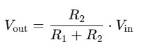
Formel des Spannungsteilers - Vin: Eingangsspannung (z. B. 5 V) - Vout: Spannung am Verbindungspunkt - R1: oberer Widerstand (Referenzwiderstand) - R2: unterer Widerstand (unbekannter Widerstand) Wenn du also den Wert von R1 kennst und Vout misst, kannst du durch einfaches Umstellen der Formel den unbekannten Widerstand R2 berechnen. Genau dieses Prinzip nutzen wir in unserem kleinen Arduino-Projekt, um Widerstände zu bestimmen – ganz ohne klassisches Messgerät.
Aufbau der Schaltung auf dem Breadboard
Die Schaltung baue ich wie immer auf einem Breadboard auf, dieses hat den Vorteil das man auf diesem recht einfach die Bauteile aufstecken und mit entsprechenden Kabeln verbinden kann. Zusätzlich verwende ich: - einen Arduino UNO R3*, - ein passendes USB-Datenkabel* - ein Acryl Board* inkl. 400 Pin Breadboard*, - diverse Breadboardkabel*, 10cm, männlich - männlich, - zwei Breadboardkabel* (schwarz & rot), 20cm, männlich - männlich, - einen Referenzwiderstand von 10kOhm* (mit 1% Toleranz), - diverse unbekannte Widerstände zum prüfen - ein Piezo Buzzer* - ein 0,96" OLED-Display* mit I2C Schnittstelle Hinweis von mir: Die mit einem Sternchen (*) markierten Links sind Affiliate-Links. Wenn du über diese Links einkaufst, erhalte ich eine kleine Provision, die dazu beiträgt, diesen Blog zu unterstützen. Der Preis für dich bleibt dabei unverändert. Vielen Dank für deine Unterstützung!

Bauteile: Widerstandsmessgerätmit Arduino Hinweis zum Piezo Buzzer Es gibt bei den Piezo Buzzer unterschiede, bei einigen ist es egal wie diese angeschlossen werden bei anderen musst du auf die korrekte Polarität achten. Dazu reicht jedoch schon ein Blick auf das Gehäuse, hier ist ein Plus-Symbol am Pin gedruckt.
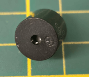
Piezo Buzzer
Schaltung
Bevor wir zur Programmierung kommen, werfen wir einen Blick auf den elektrischen Aufbau. Die gesamte Schaltung basiert auf einem einfachen Spannungsteiler, bestehend aus einem bekannten Referenzwiderstand und dem zu messenden Widerstand. Ergänzt wird das Ganze durch ein OLED-Display, auf dem der ermittelte Wert direkt angezeigt wird, sowie einem Piezo-Buzzer, der bei nahezu 0 Ohm ein akustisches Signal ausgibt. Im folgenden Schaltplan siehst du, wie alle Komponenten miteinander verbunden werden und an welchen Pins sie am Arduino UNO angeschlossen sind.
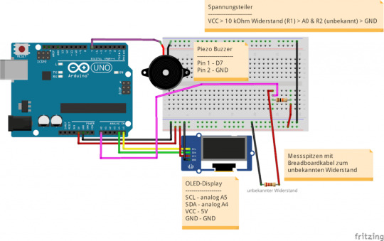
Schaltung - Arduino UNO R3 als Widerstandsmessgerät
Referenzwiderstand und Versorgungsspannung vorher genau messen
Damit die Berechnung des unbekannten Widerstands möglichst präzise erfolgt, ist es wichtig, zwei Werte vorab genau zu bestimmen: - Der Referenzwiderstand (R1) Verwende am besten einen Widerstand mit geringer Toleranz (1 % oder besser) und miss seinen tatsächlichen Wert mit einem Multimeter. Ein nomineller 10 kΩ-Widerstand kann in der Praxis z. B. 9,95 kΩ oder 10,1 kΩ betragen. Diesen exakten Wert trägst du dann im Programmcode ein. - Die Versorgungsspannung (Vin) Auch wenn der Arduino UNO mit 5 V arbeitet, liegt die tatsächliche Spannung oft etwas darunter oder darüber – abhängig von USB-Spannung, Board-Qualität und Last. Miss die Spannung am 5V-Pin des Arduino mit einem Multimeter und verwende diesen gemessenen Wert im Code, um die Spannung Vin korrekt zu setzen. Nur wenn diese beiden Werte möglichst exakt sind, ergibt die Widerstandsberechnung aus dem Spannungsteiler auch ein realistisches und zuverlässiges Messergebnis.

10 kOhm Referenzwiderstand messen

5V des Arduino UNO R3 ausmessen
Quellcode zum messen von Widerständen am Arduino
Wenn der Referenzwiderstand und die Versorgungsspannung von 5V am Arduino gemessen wurde, können wir uns dem Quellcode widmen. Dieser ist recht einfach und gliedert sich in 3 Abschnitte: - auslesen des Widerstandes, - umrechnen zu Ohm, kOhm, MOhm, - ertönen des Piezo Buzzers bei 0 Ohm (Durchgang) Für die Ansteuerung des Displays verwende ich die Adafruit SSD1306 Bibliothek welche du über den Bibliotheksverwalter der Arduino IDE installieren kannst.
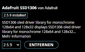

Installieren der Abhängigkeiten von der Bibliothek Adafruit SSD1306 Die Schriftart auf dem OLED-Display kannst du im Programmcode ganz einfach anpassen. Die Adafruit GFX-Library bietet dir dafür eine Auswahl an eingebetteten Fonts, die du über #include und setFont() aktivieren kannst. Je nach Displaygröße und gewünschtem Layout kannst du so eine besser lesbare oder kompaktere Darstellung erreichen. Eine Übersicht aller verfügbaren Schriftarten findest du im offiziellen Adafruit-Beitrag unter: 🔗 https://learn.adafruit.com/adafruit-gfx-graphics-library/using-fonts Dort findest du auch Beispiele zur Integration und Vorschauen der jeweiligen Schriftarten. Quellcode /*************************************************************** * Autor: Stefan Draeger * Webseite: https://draeger-it.blog * Projekt: DIY Widerstandsmessgerät mit OLED-Anzeige * Beschreibung: * Dieses Projekt misst unbekannte Widerstände mithilfe einer * einfachen Spannungsteilerschaltung und einem Arduino UNO. * Der Referenzwiderstand R1 ist exakt gemessen (hier: 9,95 kOhm), * ebenso die Versorgungsspannung (hier: 4,94 V). * Der Wert des unbekannten Widerstands wird am analogen Pin A0 * erfasst, aus 10 Messungen gemittelt und auf einem OLED-Display * angezeigt. Zusätzlich ertönt bei nahezu 0 Ohm ein kurzer Piepton, * womit sich die Schaltung auch als Durchgangsprüfer eignet. ***************************************************************/ #include #include #include #include #include // Displaykonfiguration #define SCREEN_WIDTH 128 #define SCREEN_HEIGHT 64 #define OLED_RESET -1 #define SCREEN_ADDRESS 0x3C Adafruit_SSD1306 display(SCREEN_WIDTH, SCREEN_HEIGHT, &Wire, OLED_RESET); // Pin-Definitionen #define piezoBuzzer 7 // Piezo-Buzzer an D7 #define analogPin A0 // Analogeingang zur Spannungserfassung #define debug false // Debug-Modus für serielle Ausgabe // Kalibrierte Werte für genaue Messung const float Vin = 4.94; // Exakt gemessene Versorgungsspannung (V) const float R1 = 9950.0; // Exakt gemessener Referenzwiderstand (Ohm) float R2 = -1; // Zwischenspeicher für gemessenen Widerstand void setup() { Serial.begin(9600); // Serielle Schnittstelle starten display.begin(SSD1306_SWITCHCAPVCC, SCREEN_ADDRESS); // OLED initialisieren display.display(); // Begrüßungsbild anzeigen delay(2000); // Kurze Pause vor Messung } void loop() { float newR2 = calculateR2(); // Neuen Messwert berechnen if (newR2 != R2) { // Nur bei geänderten Werten aktualisieren R2 = newR2; String value = "-undefined-"; // Einheitenerkennung und Umrechnung if (R2 value = String(R2, 1) + " Ohm"; } else if (R2 value = String(R2 / 1000.0, 2) + " kOhm"; } else if (R2 value = String(R2 / 1000000.0, 3) + " MOhm"; } else { value = String(0, 3) + " Ohm"; // Fehlerfall } if (R2 == 0) { tone(piezoBuzzer, 600, 25); // Piezo piept bei 0 Ohm } displayNewValue(value); // Neuen Wert am Display anzeigen } } // Funktion zur Anzeige auf OLED void displayNewValue(String value) { display.clearDisplay(); display.setFont(&FreeMono9pt7b); display.setTextColor(SSD1306_WHITE); display.setCursor(0, 25); display.println(value); display.display(); } // Funktion zur Widerstandsmessung mit Mittelwertbildung float calculateR2() { const int numReadings = 10; // Anzahl der Messwiederholungen float sum = 0; for (int i = 0; i int raw = analogRead(analogPin); // Rohwert vom ADC float Vout = raw * (Vin / 1023.0); // Spannung berechnen float R2 = (Vout * R1) / (Vin - Vout); // Spannungsteiler-Formel sum += R2; delay(5); // kurze Pause zur Glättung } float avgR2 = sum / numReadings; // Durchschnitt berechnen if (debug) { Serial.print("Gemittelter Widerstand: "); Serial.println(avgR2); } return avgR2; } Programm: messen von Widerstände am Arduino mit einer SpannungsteilerschaltungHerunterladen
Fazit
Das Messen von Widerständen mit dem Arduino ist dank einer einfachen Spannungsteilerschaltung unkompliziert und liefert erstaunlich präzise Ergebnisse – vorausgesetzt, man kennt den Referenzwiderstand und die Versorgungsspannung genau. Mit etwas zusätzlichem Code und einem OLED-Display lässt sich daraus sogar ein praktisches kleines Messgerät für das heimische Labor oder die Bastelkiste bauen.
Widerstand am Arduino mittels Spannungsteilerschaltung messen Trotzdem sollte man realistisch bleiben: Ein klassisches, geprüftes Multimeter bietet deutlich mehr Komfort – insbesondere durch die Möglichkeit, auch Spannungen (Gleich- und Wechselspannung) sowie Stromstärken zu messen. Solche Geräte sind bereits ab rund 15 € erhältlich und damit eine sinnvolle Ergänzung zu jedem DIY-Messprojekt. Dieses Arduino-Projekt zeigt jedoch schön, wie leicht sich mit einfachen Mitteln funktionale Tools realisieren lassen – und ganz nebenbei lernt man eine Menge über Spannungsteiler, Analogmessung und Code-Strukturierung. Read the full article
0 notes
Text
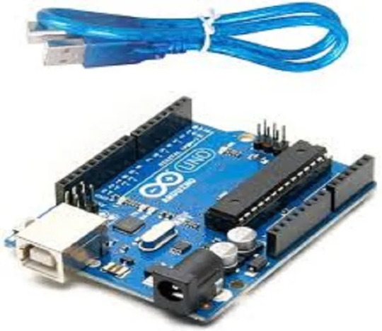
Arduino Uno
This is the board I've tinkered with in the past. I was inspired after seeing this video:
youtube
When I was playing around with it (probably around 2018, 2019ish?), I used her book to get me started:
I did eventually find the code I made on my old laptop, but I forgot to save it to the new one, whoops. I'll edit post later if I can to show it. If you're seeing this, then I never did get around to it.
0 notes